Wire colors
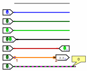
We are now in a position to summarize the full rainbow of colors that Logisim wires can take on. The following little circuit illustrates all of them at once.
-
Gray: The wire's bit width is unknown. This occurs because the wire is not attached to any components' inputs and outputs. (All inputs and outputs have a defined bit width.)
-
Blue: The wire carries a one-bit value, but nothing is driving a specific value onto the wire. We call this a floating bit; some people call it a high-impedance value. In this example, the component placing a value onto the wire is a three-state pin, so it can emit this floating value.
-
Dark green: The wire is carrying a one-bit 0 value.
-
Bright green: The wire is carrying a one-bit 1 value.
-
Black: The wire is carrying a multi-bit value. Some or all of the bits may not be specified.
-
Red: The wire is carrying an error value. This often arises because a gate cannot determine the proper output, perhaps because it has no inputs. It could also arise because two components are trying to send different values onto the wire; this is what happens in the above example, where one input pin places 0 onto the wire while another places 1 onto the same wire, causing a conflict. Multi-bit wires will turn red when any of the bits carried are error values.
-
Orange: The components attached to the wire do not agree in bit width. An orange wire is effectively "broken": It does not carry values between components. Here, we've attached a two-bit component to a one-bit component, so they are incompatible.
-
Green-Fuchsia: This color scheme indicates that the wire was selected with the tool push (
 ). This allows us to know the way and also the indication of the state of the line will be displayed in a small bubble and it also allows to follow a connection in a complex scheme.
Next: Self numbered label.