 Register
| Library : | Memory |
|
| Introduced : | 2.0 Beta 1 | |
| Appearance : |

|
|
| Logisim-clasique |
Logisim-Evolution Logisim-HolyCross |
Behavior
A register stores a single multi-bit value, which is displayed in hexadecimal within its rectangle, and is emitted on its Q output. When the clock input (indicated by a triangle ) indicates so, the value stored in the register changes to the value of the D input at that instant. Exactly when the clock input indicates for this to happen is configured via the Trigger attribute.
The R input resets the register's value to 0 (all zeroes) asynchronously; that is, as long as reset is 1, the value is pinned to 0, regardless of the clock input.
Pins
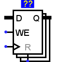
- East edge: labeled Q
- Outputs the value currently stored by the register. Bit width matches Data Bits attribute.
- West edge: labeled D
- Data input: At the instant that the clock value rises from 0 to 1, the register's value changes to the value of the D input at that instant. Bit width matches Data Bits attribute.
- West edge: labeled WE
- Input Enable: When this is 0, clock triggers are ignored. The current value continues to appear on the output. The clock triggers are enabled when this input is 1 or undefined (U). Bit width 1.
- South edge: indicated with a triangle
- Clock input: At the instant that this input value rises from 0 to 1 (the rising edge), the register's value will be updated to the value of the D input. Bit width 1.
- South edge: labeled 0
- Input Reset: Asynchronous reset: When 0 or undefined U, this input has no effect. As long as it is 1, the register's value is pinned to 0. This occurs asynchronously - that is, without regard to the current clock input value. As long as this is 1, the other inputs have no effect. Bit width 1.
Attributes
When the component is selected or being added, Alt-0 through Alt-9 alter its Data Bits attribute.
- Data Bits
- The bit width of the value stored in the register.
- Trigger
-
Configures how the clock input is interpreted. The value:
Rising edge indicates that the register should update its value at the instant when the clock rises from 0 to 1.
falling edge value indicates that it should update at the instant the clock falls from 1 to 0.
High level value indicates that the register should update continuously whenever the clock input is 1.
Low level value indicates that it should update continuously when the clock input is 0. - Label
- The text within the label associated with the register.
- Label Font
- The font with which to render the label.
Poke Tool Behavior
Clicking the register brings keyboard focus to the register (indicated by a red rectangle), and typing hexadecimal digits will change the value stored in the register.
Text Tool Behavior
Allows the label associated with the component to be edited.
Back to Library Reference