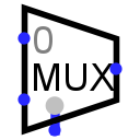
 Multiplexer
| Library: | Plexers |
| Introduced: | 2.0 Beta 11 |
| Appearance: |

|
Behavior
Copies an input on the west edge onto the output on the east edge; which of the inputs to copy is specified via the current value received through the input on the south edge. I find it useful to think of a multiplexer as analogous to a railroad switch, controlled by the select input.
(Incidentally, some authorities spell this multiplexor, but multiplexer is the predominant spelling.)
Pins (assuming component faces east, select is bottom/left)
- West edge:
-
The component input, one of which is to be routed to the output. Each input data value is numbered, starting with 0 on the north.
The number of entries is determined by the Select Bits attribute.
Bit width matches Data Bits attribute. - East edge:
-
The output value will match the input values on the west edge whose number is the same as the value currently received through the select input on the south.
If the select input contains any unspecified (i.e., floating) bits, then the output is completely floating.
Bit width matches Data Bits attribute. - South edge, left side indicated by gray circle:
-
Select input: The value of this input determines which input on the west edge to route to the output on the east edge.
Bit width matches Select Bits attribute - South edge, right side:
- Enable input: When 0, the multiplexer's output consists of all floating (U) bits, regardless of the data and select inputs. The bit width is 1.
Attributes
When the component is selected or being added, the digits 1 through 5 alter its Select Bits attribute, Alt-0 through Alt-9 alter its Data Bits attribute, and the arrow keys alter its Facing attribute.
- Facing
- The direction of the component (its output relative to input).
- Gate Size
- Determines the width of the component's design, wide or narrow.
- Select Location
- The location of the select and enable lines relative to the component.
- Select Bits
- The bit width of the component's select input on its south edge. The number of inputs to the multiplexer will be 2selectBits.
- Data Bits
- The bit width of the data being routed through the multiplexer.
- Disabled Output
- Specifies what each bit of the output should be when the component is disabled (i.e., when the enable pin is 0). Options include zero (0) and floating (U); in the latter case, the output is effectively disconnected from any other ports.
- Include Enable?
-
The component has an enable input when this attribute is
yes
The attribute is primarily for supporting circuits built using older versions of Logisim that did not provide an enable input.
Poke Tool Behavior
None.
Text Tool Behavior
None.
Back to Library Reference