 Clock
Clock
| Library: | Wiring |
| Introduced: | 2.0 Beta 13 (in Base library, moved to Wiring in 2.7.0) |
| Appearance: |

|
Behavior
The clock toggles its output value on a regular schedule as long as ticks are enabled via the option Auto-tick enabled of Simulate menu. (Ticks are disabled by default.) A "tick" is Logisim's unit of time; the speed at which ticks occur can be selected from the submenu Tick Frequency of the Simulate menu.
The clock's cycle can be configured using its High Duration and Low Duration attributes.
In the step-by-step mode the clocks advance by one tick with each keystroke.
Note that Logisim's simulation of clocks is quite unrealistic: In real circuits, multiple clocks will drift from one another and will never move in lockstep. But in Logisim, all clocks experience ticks at the same rate.
Pins
A clock has only one pin, an output with a bit width of 1, whose value will represent the current value of the clock. The location of this pin is specified in the Facing attribute.
The clock's value will toggle on its schedule whenever ticks are enabled, and it will advance by one tick each time it is clicked with the Poke tool (![]() ).
).
Attributes
When the component is selected or being added, the arrow keys alter its Facing attribute.
- Facing
- The side of the component where its output pin should be.
- High Duration
- The length of time within each cycle that the clock's output should be 1.
- Low Duration
- The length of time within each cycle that the clock's output should be 0.
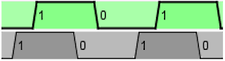
- Phase Offset
-
The phase Offset in tick of the clock. Below are two identical clock, one of which (in gray) has a phase shift of 1 tick.
- Label
- The text within the label associated with the clock component.
- Label Location
- The location of the label relative to the component.
- Label Font
- The font with which to render the label.
Poke Tool Behavior
By clicking on a clock component, you advance all the clocks by one tick.
Text Tool Behavior
Allows the label associated with the component to be edited.
Back to Library Reference