
 Pin
Pin
| Library: | Wiring | ||||||||||||||||
| Introduced: | 2.0 Beta 1 (in Base library, moved to Wiring in 2.7.0) | ||||||||||||||||
| Appearance: |
|
||||||||||||||||
Behavior
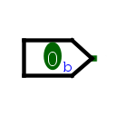
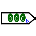
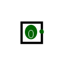
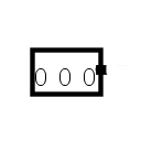
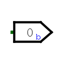
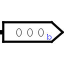
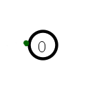
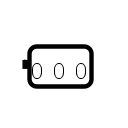
A pin is an output or an input to a circuit, depending on the value of its Output? attribute. You can observe above how Logisim represents input and or output pins according to its Appearance attribute.
In the "arrow" mode the inputs will have the connection on the pointed side and the outputs on the rectangular side. In the "classic" appearance the outputs are represented by a circle or rounded rectangle, and the input pins are represented using squares or rectangles.
In all case, the individual bits of the value being sent or received is displayed within the component (except within printer view, when the component only says how many bits wide the pin is
A pin is a convenient component for interacting with a circuit, and beginning Logisim users need not use them in any other way. But a user building a circuit using several subcircuits (as described in the Subcircuits' section of the section of the User guide. will use pins also to specify the interface between a circuit and a subcircuit. In particular, a circuit layout's pin components define the pins that appear on the subcircuit component when the layout is used within another circuit. In such a circuit, the values sent and received to those locations on the subcircuit component are tied to the pins within the subcircuit layout.
Pins
A pin component has only one pin, which will be an input to the component if the pin is an output pin, and it will be an output to the component if the pin is an input pin. In either case, its bit width matches the Data Bits attribute, and its location is specified by the Facing attribute.
Attributes
When the component is selected or being added, Alt-0 through Alt-9 alter its Data Bits attribute. Quick use of the keys allows the entry of larger values for example ALT-1 ALT-2 gives 12. The arrow keys alter its Facing attribute.
- Facing
- The side of the component where its input/output pin should be.
- Output?
- Specifies whether the component is an output pin or an input pin. Note: If the pin component is an input pin, then the pin that acts as its interface within the circuit will be an output, and vice versa.
- Data Bits
- The number of bits for the value that the pin handles.
- Three-state?
- For an input pin, this configures whether the user can instruct the pin to emit unspecified (i.e., floating) values. The attribute deals with the user interface only; it does not have any effect on how the pin behaves when the circuit layout is used as a subcircuit. For an output pin, the attribute has no effect.
- Pull Behavior
- For an input pin, the attribute specifies how floating values should be treated when received as an input, perhaps from a circuit using the layout as a subcircuit. With unchanged, the floating values are sent into the layout as floating values; with pull up, they are converted into 1 values before being sent into the circuit layout; and with pull down, they are converted into 0 values before being sent into the circuit layout.
- Label
- The text within the label associated with the component.
- Label Font
- The font with which to render the label.
- Radix
-
Allows you to define the base in which the values will be represented.
Example for 1010 in binary
Binary: 1010b
Octal: 12o
Signed decimal: -6s
Unsigned decimal: 10u
Hexadecimal: Ah
Float: 1.4E-44f Only in 32 or 64 bits of 1 or 0. Otherwise presents the value NaNf - Reset value:
- When the simulation is reset, the pin will be configured with the value of this property.
- Appearence
- There are two types of appearance, CLassic Logisim and Arrow Shapes. See the examples at the top of the page.
Poke Tool Behavior
Clicking an output pin has no effect, although the pin's attributes will be displayed.
Depending on the basis used to display spindle values, the behavior is not the same.
- Binary: If you click on one of the bits, it will change value, and if it's a tristate pin, the bit will rotate between the three values. A red marker indicates the location of the last change.
- Octal, Hexadecimal: If you click on one of the digits, it will increment by 1 and loop back beyond 7 or f as appropriate. If it's a tri-state pin, it will also go through the U state. You can use the keyboard: 0..7,U or 0..f,U to define the state of the bit under the cursor. If the data width is not a multiple of three/four, then the most significant digit will only allow the possible values for the available bits.
- Decimal, Float : An input screen appears for entering a value. For decimal values, it is possible to enter the floating-point value U. For floating-point values, it is not possible to enter this value.
You can also use the keyboard: 0,1,U to define the state of the bit under the cursor.
If, however, the user is viewing the state of a subcircuit as described in the `Debugging Subcircuits' of the User's Guide, then the pin's value is pinned to whatever value the subcircuit is receiving from the containing circuit. The user cannot change the value without breaking this link between the subcircuit's state and the containing circuit's state, and Logisim will prompt the user to verify that breaking this link is actually desired.
Text Tool Behavior
Allows the label associated with the component to be edited.
Back to Library Reference