
 Transistor
| Library: | Wiring | ||||||
| Introduced: | 2.7.0 | ||||||
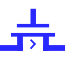
| Appearance: |
|
Behavior
A transistor has two inputs, called gate and source, and one output, called drain. When diagrammed, the source input and drain output are drawn connected by a plate; Logisim draws an arrowhead to indicate the direction of flow from input to output. The gate input is drawn connected to a plate that is parallel to the plate connecting source to drain.
| gate | gate | |||||
| source |
|
drain | source |

|
drain | |
| N-Type | P-Type |
Logisim supports two types of transistors, with slightly different behaviors described below; the P-type transistor is indicated by a circle connecting the gate input to its plate, while the N-type transistor has no such circle.
Depending on the value found at gate, the value at source may be transmitted to drain; or there may be no connection from source, so drain is left floating. The determination of transmitting or disconnecting depends on the type of transistor: A P-type transistor (indicated by a circle on the gate line) transmits when gate is 0, while an N-type transistor (which has no such circle) transmits when gate is 1. The behavior is summarized by the following tables.
| P-type | N-Type | |||||||||||||||||||||||||||||||||||||||||||||||||||||||||||||||||||||
|---|---|---|---|---|---|---|---|---|---|---|---|---|---|---|---|---|---|---|---|---|---|---|---|---|---|---|---|---|---|---|---|---|---|---|---|---|---|---|---|---|---|---|---|---|---|---|---|---|---|---|---|---|---|---|---|---|---|---|---|---|---|---|---|---|---|---|---|---|---|---|
| G | G | |||||||||||||||||||||||||||||||||||||||||||||||||||||||||||||||||||||
| S |
|
D | S |
|
D | |||||||||||||||||||||||||||||||||||||||||||||||||||||||||||||||||
|
|
|||||||||||||||||||||||||||||||||||||||||||||||||||||||||||||||||||||
Note:Since Logisim uses the markers U (high impedance / undefined) and E (Error) I have used the same in the illustrations rather than the more common Z (high impedance) and X (Error) in other documents
If the Data Bits attribute is more than 1, the gate input is still a single bit, but its value is applied simultaneously to each of the source input's bits.
An N-type transistor behaves very similarly to a Controlled Buffer. The primary difference is that a transistor is meant for more basic circuit designs.
Pins (assuming component faces east, gate line top/left)
- West edge:
- The component's source input that will transmit to the output if triggered by the gate input. Bit width matches Data Bits attribute.
- North edge:
- The component's gate input. For P-type transistors, the transistor will transmit if the gate value is 0; for N-type transistors, this will trigger the transistor if the gate value is 1. Bit width is always 1.
- East edge:
- The Drain output assumes the state of the input when the transistor is activated by the Gate input. Otherwise, it is in a high-impedance (U) or error (E) state. See the figures above for more details. Bit width is defined by the Data width attribute.
Attributes
When the component is selected or being added, Alt-0 through Alt-9 alter its Data Bits attribute and the arrow keys alter its Facing attribute.
- Type
- Determines whether the transistor is P-type or N-type.
- Facing
- The direction of the component its output relative to input.
- Gate Location
- The location of the gate input.
- Data Bits
- The bit width of the component's inputs and outputs.
Poke Tool Behavior
None.
Text Tool Behavior
None.
Back to Library Reference